seikon module
seikon is a generative module operating on both CV and audio time scales. It implements an elementary cellular automaton to generate seven digital trigger and/or gate signals and one analog trace. The user can select one out of 256 rules that define the pattern generation algorithm. Depending on that rule, the variety ranges from primitive regular patterns (rule 58) over complex quasi-periodic traces (rule 60) to actually chaotic behavior (rule 30).
If you want one, send me an email to aebsor (monkey spiral) gmail dot com.
The seikon key features:
- two digital inputs (
/and⟲) - two analog inputs (
ruandcv) - seven digital outputs (
000-006) - one analog output (
dac) - ten buttons for intuitive and fast user control
- one potentiometer to adjust the iteration frequency
inputs
ru
One out of 256 rules can be selected by the upper four buttons on the control panel.
For quick but well determined digital access, the upper four bits of the digital rule word can be cycled through by the first two buttons.
The lower four bit by the two buttons below.
The ru CV input can additionally modulate the selected rule with a rate of up to 1 kHz.
Eight LEDs indicate the rule selection in a binary way.
Grouped in two segments of four each, the rule can still be read and remembered in a graphic and intuitive way.
cv
The cv-input is a 1 V/oct voltage control input for modulating the frequency of the internal iteration clock.
The octave offset is selected by the two up and down buttons next to the frequency potentiometer.
/
The /- or clock-input allows the user to increment the internal iteration clock that can operate up to audio rate. It can therefore be used as an input for a kind of carrier frequency for the output signals. Driven with a low frequency, it can be thought of as a sampling clock of a step sequencer.
The yellow LED next to the jack lights up on a positive input signal. Holding it on a high logic level pauses the clock.
With the button below the LED, the user can execute a counter increment manually.
⟲
A rising edge on the ⟲- or reset-input resets the automaton. Also here, the LED right next to it indicates a valid reset-event and the button below this LED can trigger a reset manually.
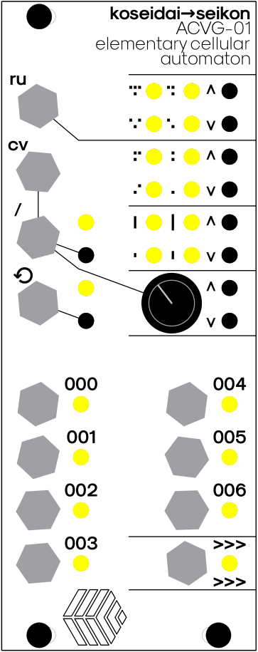
control and indicators
rule selection
The rule can be selected with the top four buttons on the panel. The upper two of those cycle through the 16 states of bit 4, bit 5, bit 6, bit 7 of the rule word, the lower two buttons through the 16 states of bit 0, bit 1, bit 2, bit 3. The current state of each group of four bits is displayed with a group of four LED left of the two buttons respectively. See below for how to interpret the rule word.
size selection
Below the four rule buttons are the two size buttons (button 5 and 6 from top) that control the size of the cellular automaton, i.e. the number of cells. One of four possible sizes (16, 32, 64, 128) can be selected. Left of the size buttons are again four LEDs that indicate the selection. The size is indicated by the bars right next to the LEDs. The longer the larger.
interpreting the rule word
In an elementary cellular automaton the binary state (either 0 or 1) of each cell depends only on its own previous state and the previous states of its left and right nearest neighbors.
Thus, for each cell there are eight possible configurations that determine its next state:
111 110 101 100 011 010 001 000
For each of this configurations, it can be chosen whether the cell is supposed to become 1 or 0 in the next iteration step.
For example, we could choose
111 110 101 100 011 010 001 000
 ↓   ↓   ↓   ↓   ↓   ↓   ↓   ↓
 0   1   1   0   1   0   1   0
Assigning one state for each of the eight possible configurations fully constrains the cell evolution.
Such an assignment is called a rule.
In the Wolfram naming scheme, the above rule is assigned the number 106, which is just the decimal equivalent of the binary code in the second row:
0 1 1 0 1 0 1 0 → 0b01101010 = 106
Rule 53 would correspond to the binary expression 0b00110101, rule 110 to 0b01101110 and so on. With 8 bits in total there are 256 possible rules.
On the left of each rule LED is a little symbol that illustrates the configuration it belongs to:
The single lower dot in each symbol represents the position of the cell in the next time step.
Above it are three possible sites that are either occupied 1 or empty 0.
They correspond to the states of the cell and its both neighbors in the previous time step.
If the LED is on, the configuration will result in an active 1 cell in the next step and vice versa it it’s off.
a few examples
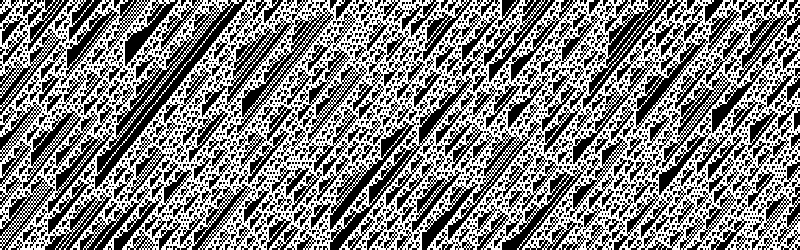
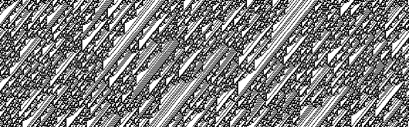
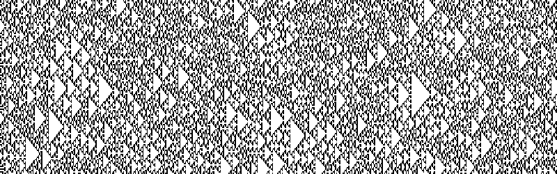
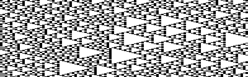
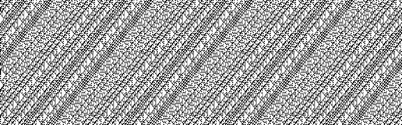
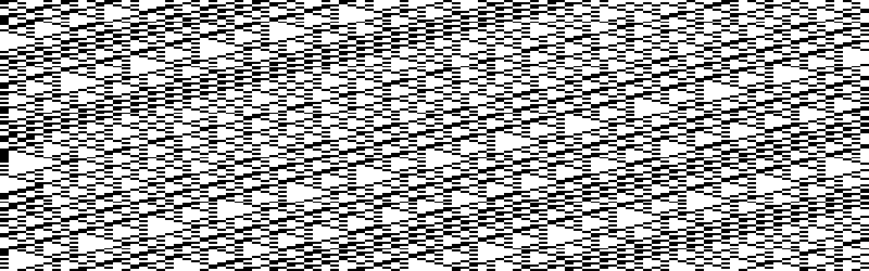
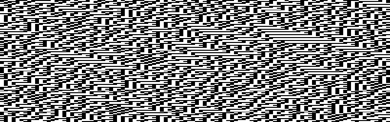
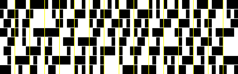
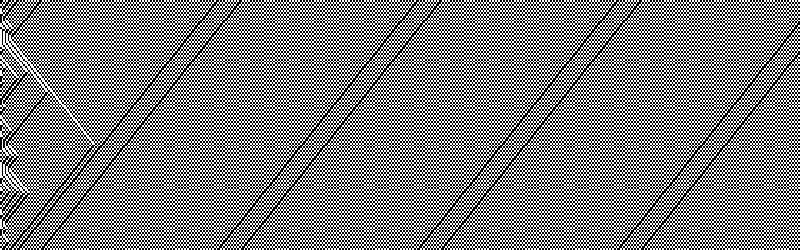
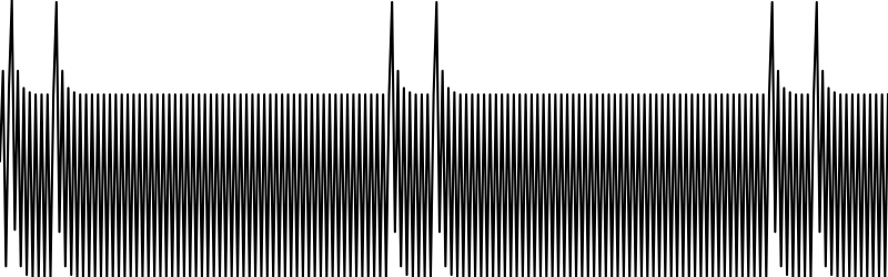
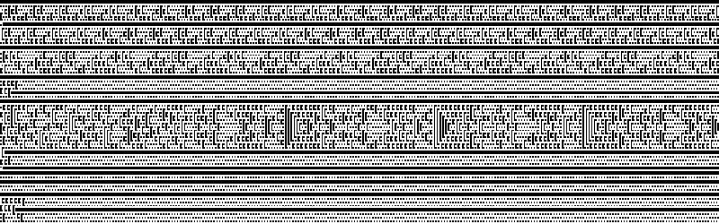
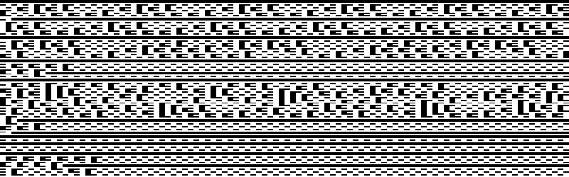
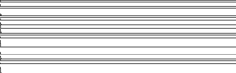
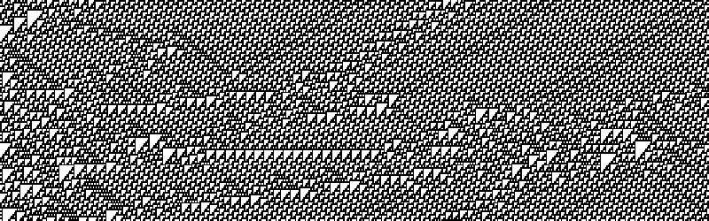
The following pictures show the time evolutions of a cellular automaton with different sizes and rules.
The first time step has been initialized with either a random array or an empty array with only the second entry set to 1.
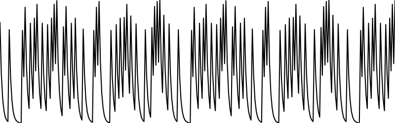
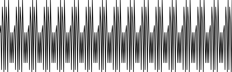
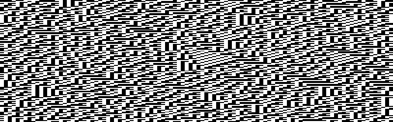
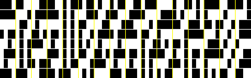
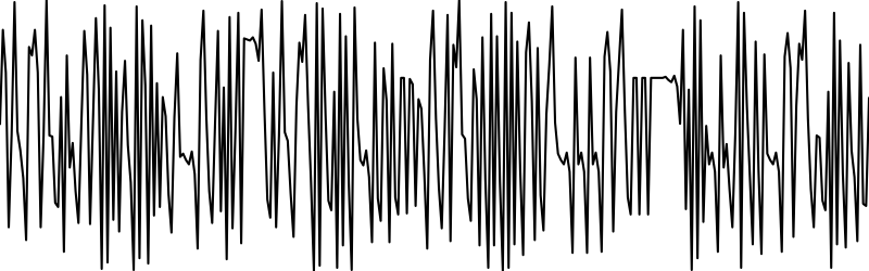
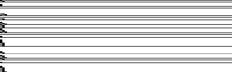
The first two images show the cell evolution for 1000 and 300 steps respectively.
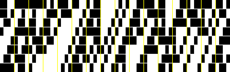
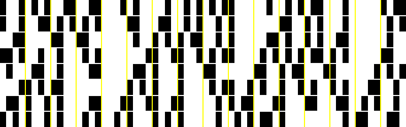
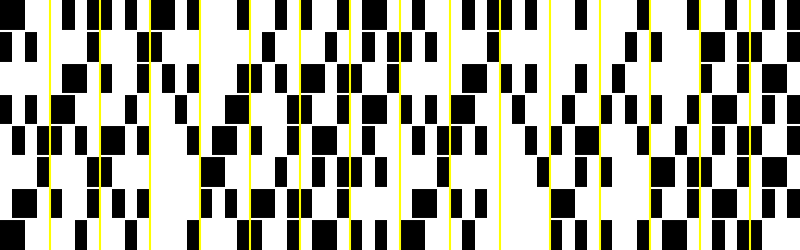
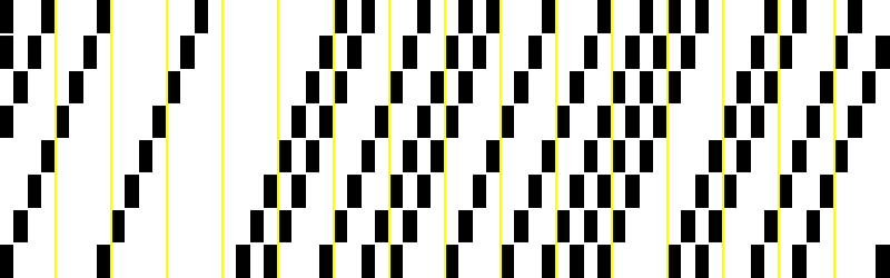
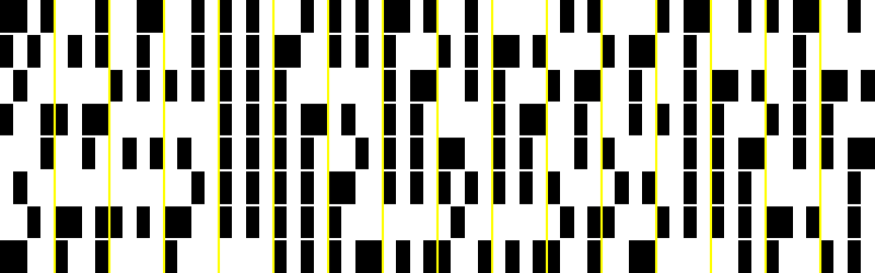
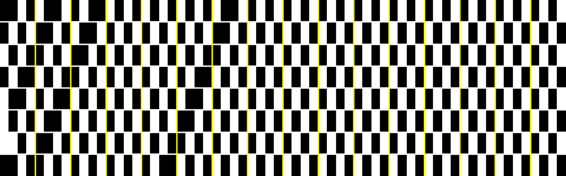
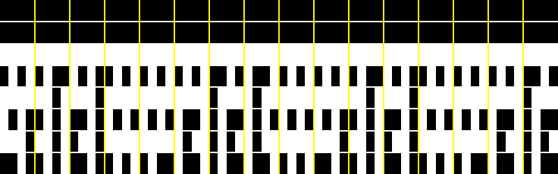
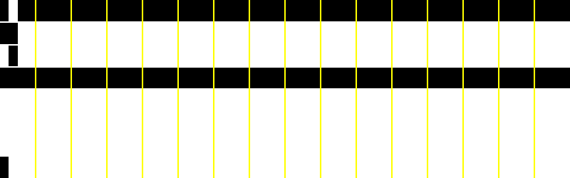
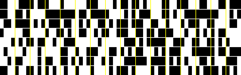
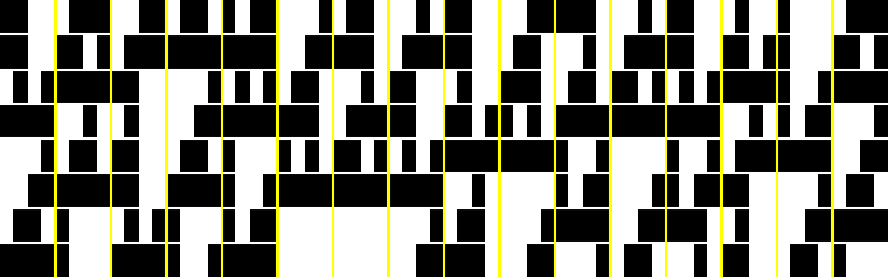
The third image shows the content of the first 8 cells with a yellow bar after every fourth clock period. These signals are provided by the seikon module and can be used for either gate or trigger purposes.
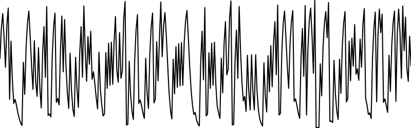
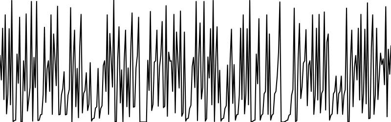
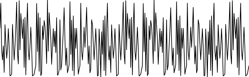
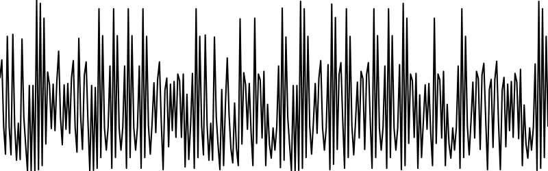
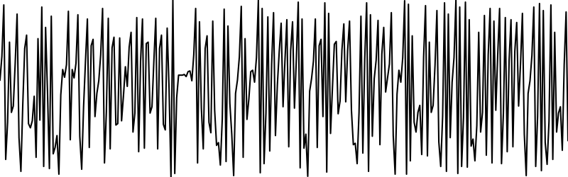
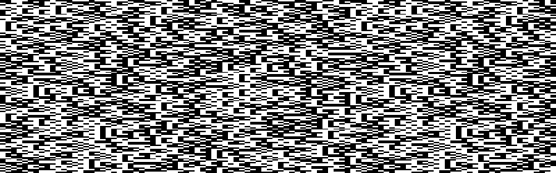
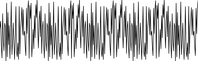
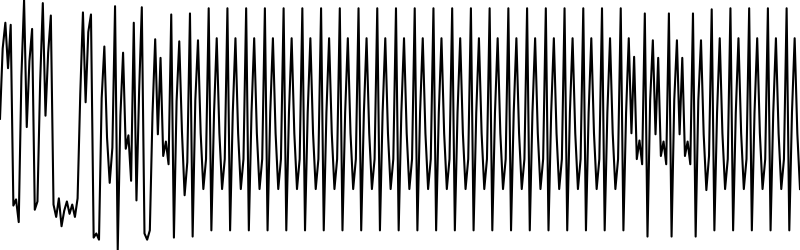
The fourth image illustrates the analog trace that is generated by the seikon module.
rule 106

rule 22
rule 26
rule 34


rule 41


rule 45

rule 57

rule 73
rule 75

rule 100

rule 105

rule 110

opposites
Every rule has something like an opposite expression. Here is rule 106 again with its “opposite” rule 169: